


So my electric saga continues, The dash boost gauge is pegged to the left, it never moves. using the wiring digram I can see why, the cables are not connected. In the picture below, the blue and brown cables are supposed to be the boost signal wire, blue cable to KRC pin 5 and Brown to something I can't figure out, in the digram it references to "Welding Point Connection with Field Indicator" C50 or C58, what does this mean?
The only wire from that connector that goes anywhere is the green one, the rpm gauge, and is connected to that red connector, according to the wiring diagram is supposed to go to DME pin 21. I do not see that red connector in any of my wiring diagrams, so I am at bit of a loss here.
I think I have other dash lights that are not working and my central warning light is alway illuminated but no other lights are on, so all this may be related.
Also in the electrical diagram there is a reference to something called HSA, it also goes to this connector and it connects to DME pin 11. I do not know what this is, ABS??
Any help would be greatly appreciated
Boost Gauge and other Dash gremlins
-
Tom

- Site Admin
- Posts: 8551
- Joined: Fri Jun 25, 2021 2:04 pm
- Location: Silicon Valley, CA
- Has thanked: 889 times
- Been thanked: 3828 times
- Contact:
What year is your car? I'm confused because it looks like you have the 4-pin square red connector from the early cars and the 8-pin black connector from the later cars (which has been cut off)??
Either way, it's easy. The boost gauge needs two signals: (1) ground, and (2) the boost signal from Pin 5 from the KLR. Use a multimeter to trace it out. These signals enter the cluster on Pins 1 and 2 of the cluster's edge connector A (behind the temp and gas gauge). In that edge connector, Pin 1 is blue on later cars and red/white on early cars. If your harness is hacked a bit, use the multimeter to figure out which wire in your pictures ohms out to pin 5 in the KLR 25-pin connector. It's either the blue wire in the black 8-pin connector or the red/white in the 4-pin red connector. Once you find that, do the same thing from the cluster side: i.e., figure out which wire in your footwell pictures ohms out to pin 1 on edge connector A. Then connect those two so that KLR pin 5 is connected to the cluster's edge connector A pin 1. That will get the boost signal to the cluster.
The boost gauge also needs its own designated ground pin on Pin 2 of the cluster's edge connector A. I believe that wire is always red/green (don't hold me to that). You want to ohm out pin 2 of the edge connector to a green/red wire in the footwell, and then make sure you connect that to a wire that ohms out to chassis ground (or just ground it yourself to the chassis). The boost gauge will not pick up ground from the cluster itself or any other source, so if you don't connect the green/red wire to ground, the gauge will be dead.
Let me know if you need more, or if I've misinterpreted that collection of wires/connectors in your picture.
Car is an 87. It came with an additional chopped up wire harness in a box and the PO had told me that it had been replaced with a new one in the car. So yeah is highly probable they replaced it with an earlier car one. Regardless your information is what I need to proceed, I will make it work.
Thank you.
Thank you.
-
Dare
- Posts: 31
- Joined: Wed Mar 16, 2022 3:03 pm
- Location: San Jose / Palm Springs
- Has thanked: 19 times
- Been thanked: 13 times
EDIT: Looks like Tom beat me to it. Anyway, hopefully this is helpful...
EDIT 2: Corrected misinformation about the MY of changes to the harness
C50 is continuation symbol indicating that the rest of the circuit continues somewhere in the area of column C, row 50 in the diagram (conveniently located on the same page). The use of a diamond shape indicates that the circuit is connected to a welding point that is shown at that coordinate.
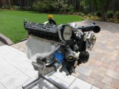
A welding point is a junction of multiple wires that is made by compressing the wires together using a press. Here is a glimpse of the positive welding point (WP #3) in the engine harness:
If you were to peal back the insulation, you would see a mass of wire strands pressed tightly together in the shape that looks like a little brick. It's essentially a form of compression weld.
In your case, the circuit in question connects to welding point #4, which is a ground junction located in the snorkel section of the engine harness. This circuit ultimately connects to a ground point at the back of the engine (MP VIII).
Based on what I'm seeing in the pictures, I'm gonna guess you have a later model 951 (87 or later), into which someone has installed an early (86) engine harness. The red 4-pin connector was present in the 86 harnesses. But at some point (MY87) Porsche switched to the black 8-pin connector.
It looks like there has been an attempt to adapt the two harnesses (the single green junction wire between the red and black connectors). But the job is incomplete. In theory it should be possible to connect the rest of the wires to restore operation of the boost gauge.
EDIT 2: Corrected misinformation about the MY of changes to the harness
C50 is continuation symbol indicating that the rest of the circuit continues somewhere in the area of column C, row 50 in the diagram (conveniently located on the same page). The use of a diamond shape indicates that the circuit is connected to a welding point that is shown at that coordinate.
A welding point is a junction of multiple wires that is made by compressing the wires together using a press. Here is a glimpse of the positive welding point (WP #3) in the engine harness:
- IMG_2474_InjectorWeldingPoint.jpg (98.55 KiB) Viewed 694 times
In your case, the circuit in question connects to welding point #4, which is a ground junction located in the snorkel section of the engine harness. This circuit ultimately connects to a ground point at the back of the engine (MP VIII).
Based on what I'm seeing in the pictures, I'm gonna guess you have a later model 951 (87 or later), into which someone has installed an early (86) engine harness. The red 4-pin connector was present in the 86 harnesses. But at some point (MY87) Porsche switched to the black 8-pin connector.
It looks like there has been an attempt to adapt the two harnesses (the single green junction wire between the red and black connectors). But the job is incomplete. In theory it should be possible to connect the rest of the wires to restore operation of the boost gauge.
Last edited by Dare on Sun Dec 14, 2025 2:23 pm, edited 2 times in total.
Thank you, this is extremely helpful. I am downloading the early car electrical diagram and with that I should be able to cross reference the connections and make this work.
You know is really a shame what "mechanics" have done to this car as far a just rigging solutions instead of doing it right, and to top it off what they charge for the work. The PO send me receipts worth over $9k on repairs to this car in the last year, she just didn't know and these people just took advantage of her. She did all this to get the car to pass California emission so she could sell it, crazy.
Again, thank you for the information above, I will post back the results.
-
Tom
- Site Admin
- Posts: 8551
- Joined: Fri Jun 25, 2021 2:04 pm
- Location: Silicon Valley, CA
- Has thanked: 889 times
- Been thanked: 3828 times
- Contact:
shft22 wrote: Fri Dec 12, 2025 6:25 am Thank you, this is extremely helpful. I am downloading the early car electrical diagram and with that I should be able to cross reference the connections and make this work.
You know is really a shame what "mechanics" have done to this car as far a just rigging solutions instead of doing it right, and to top it off what they charge for the work. The PO send me receipts worth over $9k on repairs to this car in the last year, she just didn't know and these people just took advantage of her. She did all this to get the car to pass California emission so she could sell it, crazy.
Again, thank you for the information above, I will post back the results.
Yeah, looks like quite the hack job on that harness sadly. I have to assume your oil level sender is disconnected too. If you are investing time and energy to bring the car back to top shape, consider a Kroon engine harness. They are a very faithful reproduction of the original harness, except brand new and not all dried out. Not cheap but worth it if you are restoring the car. You can fix up the old harness too, you just need to be very methodical and thorough. Gremlins hide in the least noticeable places and can cause wildly frustrating intermittent issues -- even after you've 'gone through' your harness.... Ask me how I know.
viewtopic.php?t=3477
Yeah, at some point I will remove the dash and remove the harness and decide to either redo it myself of get one from Kroon. For now I am trying to get the car going as best I can to drive it a bit and see what other gremlins show up. I had to repair the radiator fans connections, including the slow speed one, and this was next.
Mechanically, so far the car looks good, it has 140Lbs of compression and less than 5% blow-by, something that surprises me for such an old engine.
Mechanically, so far the car looks good, it has 140Lbs of compression and less than 5% blow-by, something that surprises me for such an old engine.
-
Tom
- Site Admin
- Posts: 8551
- Joined: Fri Jun 25, 2021 2:04 pm
- Location: Silicon Valley, CA
- Has thanked: 889 times
- Been thanked: 3828 times
- Contact:
Sounds like a good plan. Not sure if those are two separate projects, but just FYI you don't need to pull the dash to replace the engine harness. But if you do need to pull the dash to fix cracks, etc., here's a screw-by-screw write-up on how to do it. Not hard, just tedious...shft22 wrote: Fri Dec 12, 2025 10:59 am Yeah, at some point I will remove the dash and remove the harness and decide to either redo it myself of get one from Kroon. For now I am trying to get the car going as best I can to drive it a bit and see what other gremlins show up. I had to repair the radiator fans connections, including the slow speed one, and this was next.
Mechanically, so far the car looks good, it has 140Lbs of compression and less than 5% blow-by, something that surprises me for such an old engine.
viewtopic.php?t=341
Thank you again; the boost gauge is now working.
The blue cable from the gauge side (black 8-pin connector) connects to the green/black from the engine side (red 4-pin connector). I was able to trace this back to pin 5 on KLR. And the gray cable connects to gray. Again, I was able to trace the gray cable on the red connector to chassis ground.
So this car is an 87; the PO had the engine harness replaced, and this now has the red connector, but the harness in the dash has the black connector. This harness should be original to the car. Does this make sense?
-
Tom
- Site Admin
- Posts: 8551
- Joined: Fri Jun 25, 2021 2:04 pm
- Location: Silicon Valley, CA
- Has thanked: 889 times
- Been thanked: 3828 times
- Contact:
shft22 wrote: Sun Dec 14, 2025 1:52 pm Thank you again; the boost gauge is now working.
The blue cable from the gauge side (black 8-pin connector) connects to the green/black from the engine side (red 4-pin connector). I was able to trace this back to pin 5 on KLR. And the gray cable connects to gray. Again, I was able to trace the gray cable on the red connector to chassis ground.
So this car is an 87; the PO had the engine harness replaced, and this now has the red connector, but the harness in the dash has the black connector. This harness should be original to the car. Does this make sense?
Yes, makes sense. The original engine harness has the flat black 8-pin connector that mated to the one left hanging in your car. When they swapped in the '86 ENGINE harness, they left in the '87 DASH harness, and didn't know how to deal with the wires in those mis-matched connectors, so just cut the wires and left them disconnected. You just patched an '87 dash harness to an '86 engine harness. Good job.