


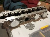
I'm interested in any differences between this and the 8v variant.
That's a cool feature that orcaslicer (based on bambu) doesn't seem to replicate. I appear to be able to do it manually with some slightly non intuitive work.
3D Printed Intake Manifolds
-
Tom

- Site Admin
- Posts: 8581
- Joined: Fri Jun 25, 2021 2:04 pm
- Location: Silicon Valley, CA
- Has thanked: 893 times
- Been thanked: 3854 times
- Contact:
I will put a 2.5 (round) and 2.7 (oval) gasket over this flange in the morning so you can see the difference. The 2.7 is somewhat close, but not exactly the same. And are you sure about Orcaslicer? I have v2.0 and it has the same connector tool as the Bambu slicer. See screen pic below from Orca...yugami wrote: Tue Jun 18, 2024 5:48 pm I'm interested in any differences between this and the 8v variant.
That's a cool feature that orcaslicer (based on bambu) doesn't seem to replicate. I appear to be able to do it manually with some slightly non intuitive work.
- orca-connectors.jpg (289.55 KiB) Viewed 1627 times
Hi Tom.
Is that a drawing or a physical piece you printed?
I can’t tell from the photo?
Thanks
Is that a drawing or a physical piece you printed?
I can’t tell from the photo?
Thanks
Tom wrote: Tue Jun 18, 2024 1:22 pm I put your STL on my Bambu X1C just to see. I had to split it in two, but Bambu adds automatic connectors that hold it together surprisingly well. I could see it being designed in 3 pieces, with the two outer ports/pieces each having two bolt holes, and the two inner ports being one piece with 3 bolt holes. I assume this is for a 16 valve head, as the ports are slightly different than either of the 8 valve ports. Printed in green ABS, since I had it spooled up and ready to go.
manifold.jpg
-
Tom
- Site Admin
- Posts: 8581
- Joined: Fri Jun 25, 2021 2:04 pm
- Location: Silicon Valley, CA
- Has thanked: 893 times
- Been thanked: 3854 times
- Contact:
The picture in post 30 is a physical piece I printed (sitting on the hood of the old Mercedes). Post 32 shows the same piece in the 3D printing software.
This is by far not a final design just working through some potential design options. I created a countersink on the flange which will give a slip fit for the "tube" going to the plenum.
Then using a few dimensions from the previous drawing provided by @michaelmount123 I created the plenum connection side and did a basic loft then an extrude to create the "tenon" for glue/solvent weld attachment.
I've messed with moving plane angles and offsets and the design ripples through fairly well, so future changes via Fusion360 shouldn't be too bad (as demonstrated by it being on the wrong side originally and I was able to flip it around to the other face and side in short order)
- Screenshot 2024-06-20 124947.png (119.73 KiB) Viewed 1478 times
-
Tom
- Site Admin
- Posts: 8581
- Joined: Fri Jun 25, 2021 2:04 pm
- Location: Silicon Valley, CA
- Has thanked: 893 times
- Been thanked: 3854 times
- Contact:
Here's the flange with a 2.5 and 2.7 gasket on top, showing the differences in ports.
- IMG_1264.jpeg (3.41 MiB) Viewed 1454 times

As a side question, what do we theorise the real difference to laptimes between ITBs and a single throttle? Obviously a pretty broad question open to speculation. I get it with n/a cars but wonder on the real world differences with a boosted engine? Especially now with dbw being an option.