To clarify what I'm referring to regarding trigger scope data above…
Since you said you are using an OE sensor, you're using a variable reluctance (VR) sensor. That means the sensor outputs an A/C voltage with an amplitude as a function of speed (speed at which the falling edge of a tooth passes by).
When using a VR sensor the ecu needs to know at what voltage to start "arming" the circuit which looks for a falling edge of each tooth (point at which the signal crosses zero again). This arming voltage typically needs to be about 50% of the peak voltage. Meaning, if for example you find that your peak voltage output from your crank sensor while cranking the engine is 6V, then your arming voltage will need to be 3V at ~400 - 600rpm (typical cranking speed for our engines
I think).
Where this can become tricky is at these low voltages we see during cranking. Unless it is documented in your ECU's help section, only the engineers who designed your ECU HW/SW will know the minimum arming voltage an ECU needs in order to give it enough time to "arm" itself and start its internal processing for recognizing a zero cross point (tooth passing by) to then calculate an engine speed and subsequently use the reference sensor trigger to understand where the engine is in its 720deg cycle so that ignition can happen at the correct point according to the ignition timing table (critical to actually start combustion and start the engine…).
So if your gap is too large, your peak output voltage amplitude from your crank sensor will be very low, if it is so that that there is not enough time for the ecu to calculate engine speed, then you will never be able to start the engine.
Here is an example from my ECU when I went through this process:
Crank sensor gap was 0.89mm. Peak amplitude was ~0.2V. This was so low that with an arming voltage at 0.1V (50% of 0.2), the ECU had a hard time properly calculating engine speed, and as such would not start.

- 0.89mmgap.png (135.66 KiB) Viewed 2064 times
Crank sensor gap was 0.5mm. Peak amplitude was ~0.65V. With an arming voltage of 0.3V, the ECU can properly calculate engine speed no problem.
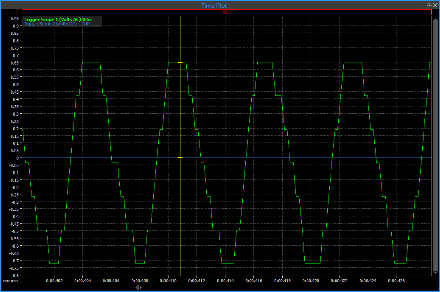
- 0.5mmgap.png (131.53 KiB) Viewed 2064 times
My current arming voltage calibration table for reference. I get no trigger errors with these settings, but I would not necessarily copy paste to your ECU's calibration table. For reference only:

- armingvoltage.png (23.38 KiB) Viewed 2064 times
As FYI, in the above screen shots the trigger scope logging function actually has a pretty low logging rate, so this is why the waveform doesn't look as pretty as a traditional A/C waveform. At higher engine speeds the trigger scope does look more like you'd expect, but since we're talking cranking, the point comes across I think..
Of course, if you have wiring issues you may have a completely different problem than sensor gap and arming voltages I described above, but it is a good place to start. Especially considering you have oscilloscope data already.