I've started digging in on this a bit, and believe I have a fairly easy fix to offer that eliminates the bouncing needle (regardless of root cause). I'll post that in the next day or two when I have time to write it up and more fully test it. For now, I thought I'd share some basic info about the gauge since I couldn't find it anywhere on the internet and had to sort it out to get to the bottom of the needle jitters.
The gauge has three inputs: 12 volts, ground, and the sender pressure signal (post G, blue/white wire). The pressure signal is just a variable resistor to the case/block; the higher the pressure, the higher the resistance. For bench-testing the gauge itself, here are the pin-outs...
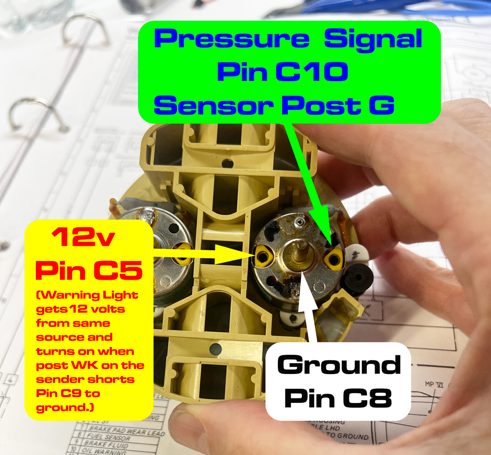
- oil-pressure-sender-pin-out.jpg (610.18 KiB) Viewed 1259 times
The pin numbers are to edge connector C behind the cluster (the one on the oil pressure side of the cluster). You can test by applying 12v and ground to their respective terminals, and connect the sensor input to ground via a potentiometer or resistors to make sure the gauge reads what it should (per the chart below) at the various resistance levels.
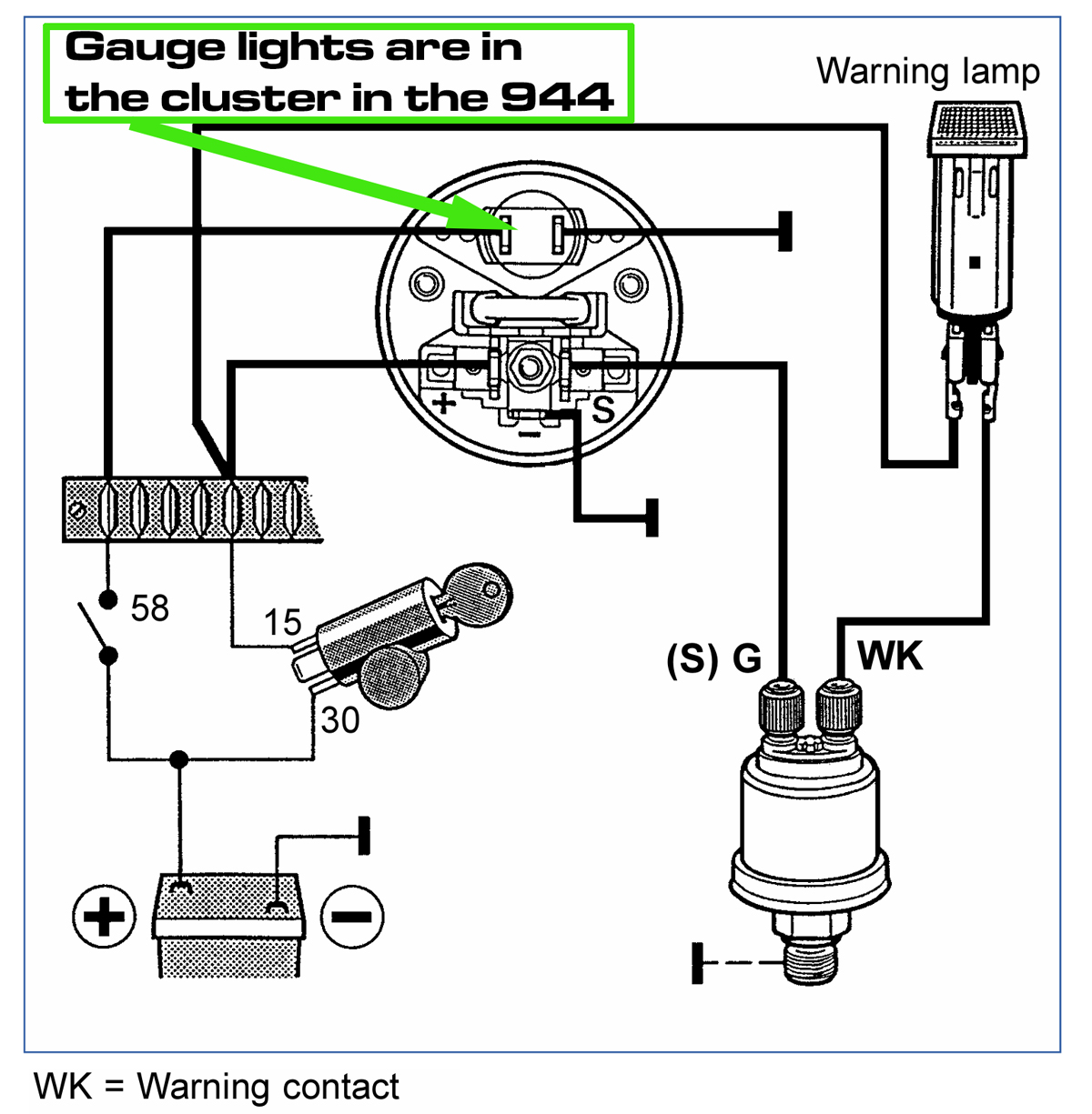
- basic-oil-pressure-gauge-layout.jpg (339.86 KiB) Viewed 1259 times
Here's a similar VDO gauge diagram. The top connection is just a light for the gauge, since this diagram is for a stand-alone gauge. Other than that, this is the same as the 944 oil pressure gauge. Note the warning light is not really part of the gauge at all. The WK post on the sender simply shorts to ground when the pressure is too low, completing the circuit to the warning light bulb in the cluster.
The manual sets out the reference specs as:
1 Bar = 29.6 ohms
2 Bar = 65.3 ohms
3 Bar = 98.9 ohms
4 Bar = 133.6 ohms
5 Bar = 184 ohms
The gauge works by balancing the pull of multiple electromagnetic coils inside the gauge. To visualize the basic idea, you can think of it like this: when powered up, one coil -- let's call it the base coil -- is always powered and creating a magnetic field that pulls the needle up. The sender supplies ground to another magnetic coil -- let's call it the control coil -- that pulls the needle down. This means the control coil gets more and more current, and the needle goes lower and lower, as the pressure and resistance go down. It's more complicated than that, but that's the gist, and explains why a disconnected or dead sensor pegs the needle high -- since there is nothing to counter-act the base coil pulling the needle up. Similarly, if the sender or wire shorts to ground, it supplies max current to the control coil, forcing the needle all the way down. (A clever side-effect of this arrangements is that the gauge is not affected by voltage fluctuations.)
The design is intended to damp the needle so it doesn't over-swing and jitter, instead keeping it locked in a smooth, magnetic tug-of-war. So why does it jitter? I suspect several things can contribute, including a jittery sender, poor connections, pressure pulsing at low pressures, poor grounds, etc. So all the normal advice is worth trying -- cleaning grounds, cleaning the football connector contacts behind the gauge, checking the sender itself, etc.
But if all that fails, I think in many cases the gauge itself is just old. The slightest amount of friction on the needle's axle can contribute to bouncing. And after 40 years, it's a near certainty the axle won't be as smooth and turn as freely as it did when new. So when the needle sticks (ever so imperceptibly), it doesn't move until the force builds up enough to break it free. At that point, the needle breaks free and over-shoots its target, causing the bounce. Kind of like a sticky crank-open window -- to open it one inch, you have to push hard on the crank until it suddenly pops out and bounces back and forth until coming to a rest. That's my theory anyway, and I'm 'sticking' to it

The solution I've come up with works regardless of the root cause, however, so even if I'm off base with that theory, my approach will eliminate the bounce. Stay tuned for that...


